
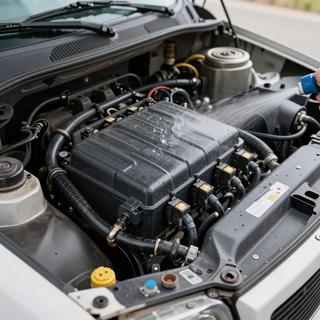
To wash a truck engine with a garden hose without damaging the electrics, cover and seal the fuse box and every harness connector in the engine bay first, then run the hose at low pressure with no high-pressure nozzle fitted. Doing it the other way round is the most common cause of avoidable electrical failure in fleet trucks: a pressurised jet drives water past connector seals and into terminal cavities, and the fault often shows up days later.
Engine bay cleaning therefore starts with isolation, not water. Wrap the fuse box and tape it shut; inspect each harness connector, bag it, and secure the bag so runoff cannot track along the loom toward a sensitive module. An unrestricted garden hose still delivers plenty of volume at low velocity – enough to lift road film without the spray speed that forces moisture into sealed assemblies.
The order does not change: cover and seal, pre-rinse from a distance, clean top-down, rinse, dry, inspect, document. Grease and tar on the block and frame rails come off with the same methods used anywhere else on the truck, provided the electrical protection stays in place throughout.
For a fleet the payoff shows up as fewer electrical faults, fewer unplanned workshop days, and a procedure any driver or yard technician can follow without being told twice.
Pre-Wash Preparation and Safety: Setting Up a Low-Pressure Engine Wash
A low-pressure engine wash begins long before the hose is opened. Switch the engine off and let it cool until the cylinder block and exhaust manifold are cool to the touch, because a warm casting turns water into vapour and pushes moisture into electrical cavities that would otherwise stay dry. Where the manufacturer’s procedure allows it, isolate the battery and confirm no accessory circuit is still live, and keep the keys with the technician doing the work for the duration of the task. Look for fuel, oil and coolant leaks and correct any active seepage before a drop of water goes near the bay, since a hose stream will carry contaminated fluid across the compartment and into yard drainage. Knowing the usual methods for grease and tar removal also helps you match the wash to the contamination that is actually there.
Work through the following sequence without deviation.
- Park the vehicle on level ground with clear drainage, so runoff collects predictably and cannot pool beneath the sump.
- Isolate the battery and confirm that no live accessories, interior lamps or auxiliary circuits remain energised.
- Check that all caps and dipsticks are fully seated: oil filler, coolant, washer fluid and transmission dipstick.
- Cover the fuse box completely with a waterproof barrier that will not lift under spray.
- Cover harness connectors and sensor plugs, starting with the ones in the lower half of the compartment.
- Shield the air intake and breather so that no water can enter the induction path.
- Confirm the hose has no pressure-boosting nozzle attached and is delivering at mains pressure only.
- Stage drying cloths and moisture-displacing spray within reach before the water is turned on.
The order follows the risk: vehicle stability and electrical isolation first, protection of sensitive components next, control of the water source last. Cloths are staged before the first drop falls so that nobody leaves a panel wet while searching for a rag.
Covering the Fuse Box and Harness Connectors
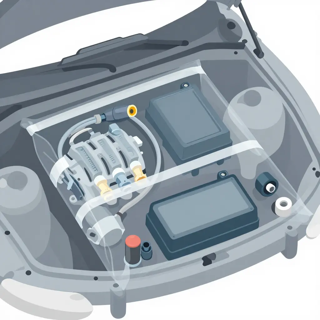
Isolate the electrics before any water appears. The fuse box and every harness connector stay dry for the full duration of the wash.
Sealing the Fuse Box
Take the lid off only if you need to look inside. If you do not, leave it seated and go straight to sealing. If you do, check that every fuse and relay is seated before the lid goes back on.
Seal the box with a clean plastic bag or a purpose-made cover, sized so it overhangs the housing on all four sides. Fold the surplus flat against the housing and tape the seams with low-residue tape. Run the tape continuously along each seam rather than spot-taping it, and press it down firmly, because water running down a panel will find the smallest gap. The bag is not the seal; the tape is.
Wrapping Harness Connectors
Wrap each exposed connector and sensor plug individually. A bag suits large connectors; marine-grade sealing wrap is the better choice for small plugs, multi-pin sensors and tight clusters. Tape each wrap closed and point the opening downward, or seal it completely. Most water arrives from below, where spray deflected off the block, sump or frame rail travels upward and pools in an open connector body.
Shielding the Remaining Components
Cover the alternator, the starter solenoid area, the ECU cavity and any open relay sockets. Covers should shed water rather than trap it. Check that every cover is seated before the nozzle is opened.
Retaining and Removing Covers
Leave covers on for the whole wash, including the final rinse. Once the hose is off, take them off: a sealed bag holds the moisture it was meant to keep out, and condensation has nowhere to go. Drying and inspection both happen with the covers removed, and wet bags go in the bin rather than back in the van.
Spray Discipline
Never spray straight at a covered component, because a direct jet forces water past taped seams and into connector bodies. Aim at the metal around the part and let runoff carry the contamination away. Heavy deposits on surrounding metal come off with the same grease and tar techniques used elsewhere, applied before the bay gets wet rather than during the wash.
Get the covering wrong and you get corrosion at pins and terminals, tracking across damp connector faces, and intermittent faults that will not reproduce in the workshop. The diagnostic time that follows usually costs more than the wash saves.

The schematic sets out what has to be true before the first drop leaves the hose: fuse box and connectors covered, so spray is deflected instead of absorbed.
How to Wash Truck Engine with Garden Hose
With the fuse box and harness connectors covered, a technician can wash the engine on site with a garden hose and no pressure washer, provided the engine is cool enough to touch.
Stage 1 – Pre-Rinse From a Distance
Hold the hose at least one metre from the compartment and use the lowest flow the nozzle will give. The aim is to soften dust and road film, not to blast it off. Work top-down and front-to-back, so loosened material runs off surfaces you have already cleaned instead of washing back over them.
Stage 2 – Clean in Sections
Wash one section at a time: the front of the block, one side, the opposite side, then the firewall. Finish each section before starting the next, so that no part of the bay stays wet longer than it has to. Standing water is what lets moisture travel into cavities and sit against connectors.
Stage 3 – Control Angle and Direction
Keep the spray at a shallow angle to the surface, closer to a sweep than a jet. Do not aim into seams, connectors or the fuse box, and do not hold the nozzle still on one spot. A glancing pass lifts contamination; a perpendicular blast pushes it inward.
Stage 4 – Limit Total Exposure
Set a firm time limit for the whole wash and stop once the visible contamination is gone. Exposure time is the variable an operator controls most directly, and a short wash beats a long soak every time.
Stage 5 – Apply and Rinse Degreaser
Use a low-foam degreaser only where the surface can take it – cast metal, painted panels, hoses built for it – and never on electronics, open terminals or labels. Respect the manufacturer’s dwell time and rinse inside it, at the same low flow and shallow angle. On heavily soiled areas, read the notes on removing grease and tar from truck surfaces before leaving the product on longer.
Four Pressure and Angle Rules
- Use the lowest achievable flow setting throughout, including the final rinse.
- Keep the nozzle at least one metre away during pre-rinse and rinse passes.
- Hold the spray at a shallow angle to the surface, never perpendicular.
- Never direct a jet into seams, connectors or the fuse box.
Record each completed wash against scheduled fleet maintenance intervals, so engine cleaning sits in the same record as other inspection and service work rather than happening whenever someone gets round to it.
How much water a component tolerates varies across the bay, and the covering should match that tolerance instead of treating the whole compartment alike. Fleets that write these steps into a standing wash protocol find it easier to keep engine cleaning consistent with broader truck wash compliance and emissions rules.
Engine bay components: cover or leave exposed
| Component | Water sensitivity | Required covering method | Risk if left exposed |
|---|---|---|---|
| Fuse box | High; a directed jet bridges contacts | Seal in plastic sheeting; tape all edges | Blown fuses, corroded terminals, immobilised vehicle |
| Harness connectors and sensor plugs | High; moisture corrupts low-voltage signals | Bag each connector; secure with cable ties | Fault codes, erratic readings, hard starting |
| Electronic control unit cavity | Critical; the housing is sealed against splash, not against a directed jet | Cover with waterproof sheet; no direct spray | ECU failure, costly replacement, extended downtime |
| Alternator | Moderate; water reaches bearings and windings | Shield with plastic; limit spray duration | Bearing noise, charging failure, shortened service life |
| Starter solenoid | Moderate; terminals corrode and stick | Cover terminals; avoid direct stream | Solenoid seizure, cranking failure, terminal corrosion |
| Air intake and filter housing | High; ingested water damages the engine | Cap intake; inspect filter seals before washing | Hydrolock, saturated filter, internal engine damage |
| Breather and dipstick openings | High; water contaminates the lubricant | Cap breather; reseat dipstick fully | Water in oil, sludge formation, accelerated wear |
| Relay and terminal blocks | Moderate to high; exposed contacts oxidise | Wrap blocks; tape any loose covers | Oxidation, intermittent faults, relay failure |
| Painted or decaled exterior surfaces | Low to moderate; no electrical exposure | No cover required; wash last and rinse promptly | Faded decals, water spotting, dulled paint |
The table reduces to one rule: cover anything that carries current, holds fluid or admits air, and leave exposed only surfaces where moisture is a cosmetic problem. Where the classification is uncertain, cover the part, because a couple of minutes with tape costs far less than an ECU replacement and a truck parked at the depot.
Drying and Post-Wash Inspection After a Low-Pressure Engine Wash
Drying is a stage of the procedure, not the gap between washing and inspecting. Work through it in order, and do not release the vehicle until the sequence is signed off.
Drying Sequence
1. Remove standing water. Use compressed air at reduced pressure to push pooled water out of recesses, rails, the valley between the cylinder banks and the top of the transmission housing. Keep enough distance that you do not drive water into sealed components.
2. Wipe accessible surfaces. Work from the highest point downward with clean absorbent cloths, replacing them as they load up rather than redistributing moisture across dry panels.
3. Allow residual moisture to evaporate. Leave the hood open for the drying period set out in the site procedure. Closing it early to recover time traps vapour, which recondenses on cool internal surfaces.
4. Apply moisture-displacing spray. Treat connectors and terminal blocks only once the surrounding surfaces are dry, because on a wet surface the spray seals moisture in instead of displacing it.
Inspection Sequence
- No water in the fuse box cavity, including the base of the enclosure and the relay seating area.
- Every harness connector dry and fully seated, with retention clips engaged.
- Every cover removed for the wash refitted in full: ECU covers, fuse box lid, battery box closures.
- Engine starts and runs with no stored or active fault codes before the vehicle returns to service.
A connector holding moisture, or showing corrosion discolouration, is a defect. Record it and refer the vehicle to maintenance; it does not get cleared for dispatch on the assumption that it will dry in service.
Where pre-wash contamination is heavy, pair this routine with these degreasing techniques, so inspection time goes on verifying condition rather than correcting incomplete cleaning.
Record the drying start and finish times, the inspection result and any defect referral on the wash log. That entry is the evidence the sequence was completed and the unit was released on a verified basis.
Maximum Safe Spray Pressure by Engine Bay Component
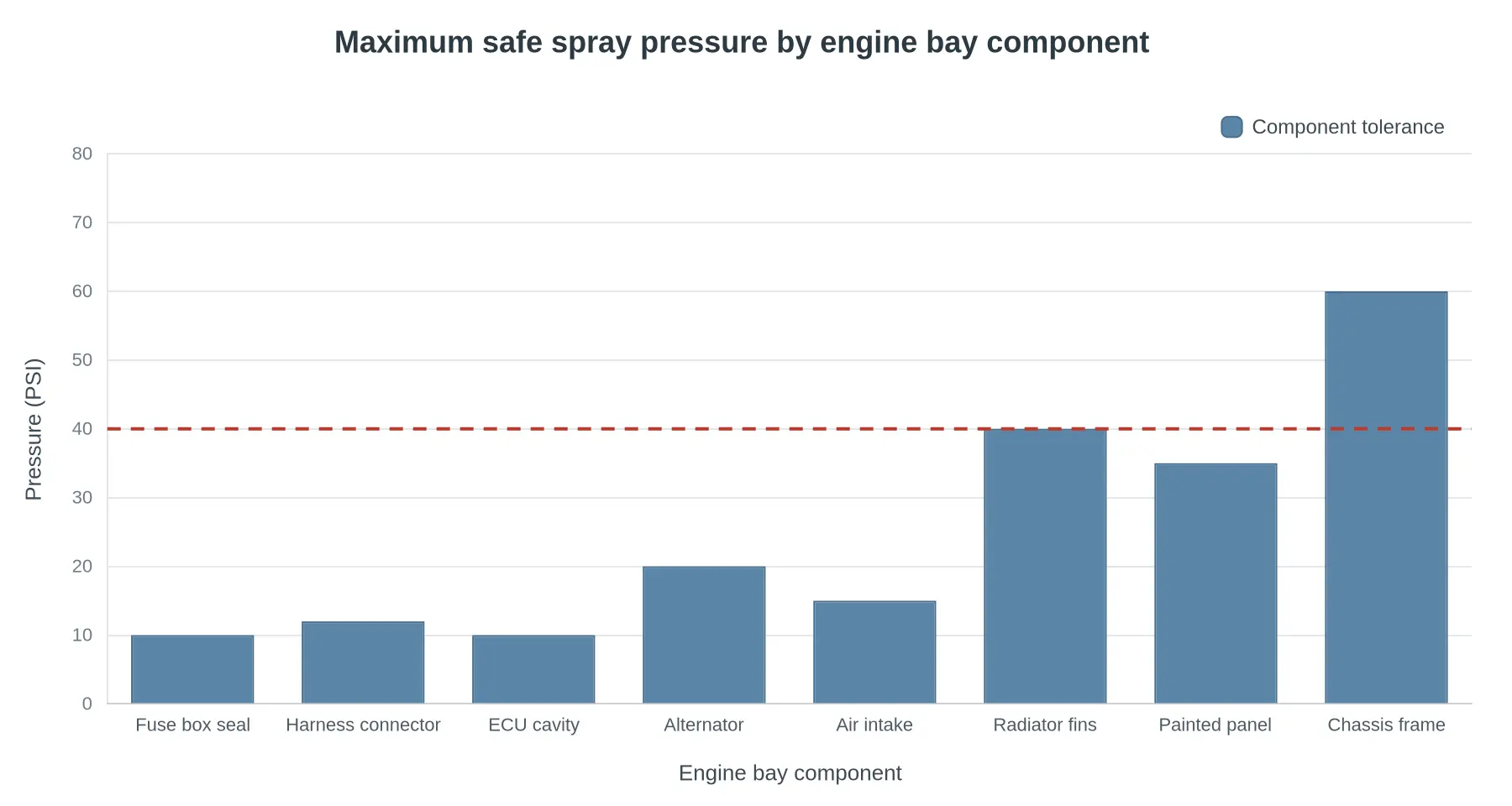
Chart: Component pressure tolerances of 10-60 PSI plotted against a 40 PSI garden hose reference line.
Caption: The chart puts component tolerances between 10 and 60 PSI against a typical 40 PSI garden hose. An intact seal holds at that pressure; an aged, damaged or unsealed one does not, which is why the covering comes before the water and the nozzle stays back.
Selecting and Diluting the Right Degreaser for a Garden-Hose Engine Wash
An engine compartment holds electrical connectors, rubber hoses, painted surfaces and a film of oil contamination in the same space. A cleaner that works well on a workshop floor can be the wrong product here. Choose a degreaser that is labelled for engine compartments, low-foaming and electrically safe. Low foam matters with a garden hose: without high-pressure flow, foam lingers on the surface, holds soil and takes longer to rinse out. Check the label for compatibility with aluminium, wiring insulation, connector boots and paint. Keep solvent-based products away from harnesses, sensor leads and rubber hoses, because aggressive solvents soften insulation and accelerate seal deterioration. Wiring, seals and fuel-system parts, including the diesel engine lift pumps covered in this component guide, are the most exposed to chemical attack.
Dilution matters as much as product choice. Mix the concentrate to the manufacturer’s stated ratio with clean water. Stronger mixes do not clean faster; they leave concentrate residue in seams and textured surfaces, which then attracts dust and holds moisture against connectors and metal. That residue can also dry into a film that a low-pressure hose struggles to shift.
Before you apply anything, confirm the fuse box and harness connectors are covered. Apply the diluted product with a hand sprayer rather than pouring it onto the engine. A sprayer gives you localised control and keeps you from flooding an electrical enclosure or soaking sound-deadening material. Use a coarse mist, keep the nozzle moving, and aim at greasy surfaces rather than into fuse boxes, connectors, alternators or the intake. Respect the dwell time: let the product work, but do not let it dry on the surface. Work in sections you can finish, so re-wetting is unnecessary and runoff stays contained.
For heavy deposits, pair the correct dilution with the targeted methods in these proven approaches to grease and tar. Match the agitation to the surface, and keep stiff brushes away from wiring and soft rubber.
Rinse with the same low-pressure setting you used for pre-rinsing. A broad fan pattern and a steady distance flush loosened soil and chemical residue without forcing water into sealed components. Rinse until the runoff runs clear, then check the seams and lower ledges where residue collects. A complete rinse protects the engine surfaces and the electrical system around them.
The Five-Stage Engine Bay Wash Sequence
A garden hose, a low-pressure nozzle and a little patience will handle most of the job, provided you work in the right order. The diagram below reduces the method to five steps, from protecting sensitive components to signing off the inspection.
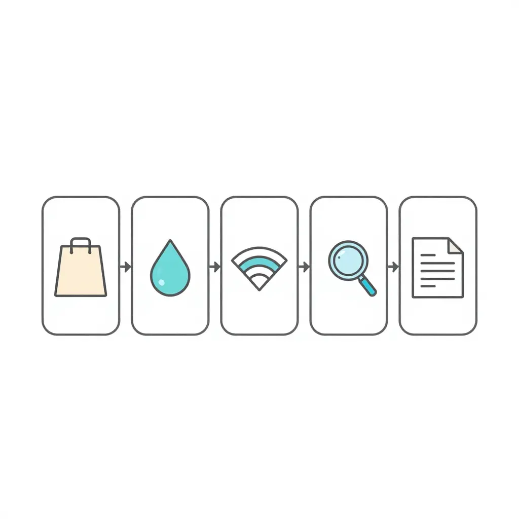
| Stage | Action | Fleet-Critical Detail |
|---|---|---|
| 1 | Cover | Bag the fuse box, seal harness connectors and air intake before any water flows |
| 2 | Wash | Low-pressure mist from the top down, working away from electrical components |
| 3 | Dry | Air-dry or wipe residual moisture out of recesses and connector boots |
| 4 | Inspect | Check for water ingress, cracked looms and loose grounds before start-up |
| 5 | Document | Log the wash, the products used and any defects found for audit purposes |
Most costly mistakes start at stage one: one soaked harness connector turns a fifteen-minute wash into a roadside breakdown and a missed delivery window. Treat the sequence as fixed, and brief every operator on it, particularly the covering step, which is the easiest one to rush. If crews are also fighting baked-on contamination on the block and chassis, these methods for cleaning grease and tar fast are worth adding to the same standard operating procedure.
Common Mistakes in Garden-Hose Engine Washing
- Washing the bay before the fuse box is covered. Water lands on relays, fuses and blade terminals, capillary action holds it against live contacts, and corrosion or a short follows. Wrap the fuse box, battery terminals and exposed harness junctions in plastic and tape them before any water is applied.
- Fitting a pressure-washer nozzle or high-pressure lance to a garden hose. Discharge pressure rises beyond the low-flow envelope the seals were designed for, forcing water past O-rings and connector boots. Keep the standard open-ended hose nozzle and rely on flow volume rather than force.
- Spraying upward into harness connectors and sensor plugs. Water is pushed against gravity into cavities that drain poorly and stays around the pins. Hold the nozzle level or angled downward and never aim at the underside of a connector body.
- Leaving the bags and covers on through the drying phase. A closed wrap holds condensation against the component it was meant to protect. Remove all covers once the final rinse is finished, before drying begins.
- Restarting the engine while the bay is still wet. Splash and fan airflow carry water into the intake tract, the alternator and belt-driven accessories. Clear the compartment with compressed air and cloths, and let it ventilate until visibly dry before the key is turned.
- Over-diluting or under-rinsing the degreaser. A weak mix will not lift road film, and a strong one leaves residue that attracts dust and attacks rubber. Mix to the stated ratio and rinse until the runoff clears, using these grease and tar removal methods where deposits are heavy.
- Skipping post-wash documentation. Without a record, nothing later links an electrical fault to the wash date, the components protected or the damage already present. Log a short entry for every unit: date, protective measures taken, pre-existing damage.
All seven share one control principle: water goes only onto surfaces that drain and dry, and anything that cannot drain is isolated before the wash and inspected after it. Applied consistently, that sequence turns a routine cleaning task into a controlled procedure with a traceable record, which is the minimum a fleet manager should accept for equipment carrying commercial load.
Where the Water Actually Gets In
Before you point a garden hose at a warm engine, it helps to know which components fail first. The chart below ranks water intrusion points in a typical truck engine bay by share of incidents.
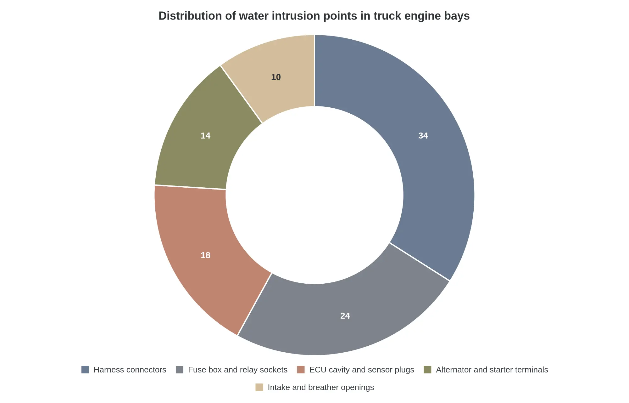
Together, harness connectors (34%) and fuse box and relay sockets (24%) account for more than half of all water intrusion points, which is precisely why those two elements must be covered first before any hose is turned on.
The five segments are not evenly spread, and that unevenness is the useful part. Harness connectors and fuse box and relay sockets together make up 58% of the intrusion points in the chart, so covering those two first deals with most of the exposure in a step that takes minutes. That is a fair return for a supervisor protecting a vehicle from an avoidable electrical fault.
Frequently Asked Questions: Washing a Truck Engine with a Garden Hose
Engine bay cleaning means removing road grime, oil film and dust from a truck’s engine compartment with low-pressure water and approved degreasers. It is scheduled maintenance, with fixed rules about what gets protected before the water is turned on.
Can a garden hose deliver enough pressure to damage engine electronics?
No. A garden hose delivering 40 to 60 psi will not crack an ECU housing or force water through an intact seal. The real hazard is volume and direction: a steady stream aimed at an unprotected fuse box or an open connector floods it within seconds. The rule for fleets is simple: wash a truck engine with a garden hose only when the electronics are covered and the spray stays low and moving.
What has to be covered before washing?
The fuse box, every harness connector, the ECU, the alternator, the starter, the air intake opening, battery terminals and any aftermarket wiring. Plastic sheeting secured with clips or purpose-made waterproof caps both work, provided nothing shifts under spray. Seal the air intake first, because water drawn into the intake is the fastest route to a hydro-locked engine.
How often should a truck engine bay be washed?
Set an interval that matches the duty cycle: quarterly is a common starting point for highway fleets, monthly for construction, mining and aggregate units working in mud, salt and dust. Add a wash after any fluid leak repair, before a compliance or safety inspection, and whenever heavy chemical residue is present. Do not wash on appearance alone, because a clean-looking bay can still hide a cracked connector.
What should be done if water reaches a harness connector?
Stop washing and do not start the engine. Separate the connector, blow it out with compressed air, apply an electronics-safe contact cleaner, and dry it fully before reconnecting. Check the pins for corrosion, record the incident in the maintenance log, and have the circuit tested before the truck returns to service.
Is a pressure washer ever acceptable?
Not for routine engine bay cleaning in a fleet setting. High-pressure nozzles drive water past lip seals, weather-pack seals and grommets, and the damage usually appears weeks later as an intermittent fault on the road. If a workshop supervisor explicitly authorises high pressure for heavy grease on the block, restrict it to a wide fan tip held at least one metre from any electronics.
Who should authorise and perform the wash?
The fleet manager or workshop supervisor authorises the work, and a trained technician or wash-bay operator performs it. Drivers should not wash truck engine bays unsupervised. Authorisation, products used and completion time go in the maintenance log, and fleets can align the procedure with truck wash industry compliance and emissions regulations.
Converting the Procedure into a Fleet Policy
A procedure protects a truck only when it is applied the same way every time, so these steps belong in a written fleet policy that covers every vehicle, every shift and every operator, rather than in individual judgement. Four elements make the policy enforceable.
- A written pre-wash checklist. No wash begins until the checklist is completed and initialled. It names the fuse box and the harness connectors as mandatory cover points, so operators confirm by name which components are sealed before any water is applied. Covering them is not housekeeping; it is what separates a routine engine-bay clean from an avoidable electrical failure.
- An approved equipment list. Engine washing is limited to a hose fitted without a booster nozzle and set to a low-pressure setting, and nothing else is authorised. Restricting the nozzle type and the pressure removes the most common cause of water intrusion into sealed connectors, and keeps behaviour consistent across depots and shifts.
- An inspection sign-off after every wash. Each wash closes with a documented inspection confirming that covers have been removed, that no standing water remains, and that the engine starts and runs normally. The sign-off is recorded by the person who performed the inspection, not the person who performed the wash.
- A records entry. Every wash generates a record with the date, the operator and any defects found, which turns individual washes into a maintenance history that supports fault tracing, warranty discussions and audit.
| Record field | What must be captured |
|---|---|
| Date | Wash date and shift |
| Operator | Name or staff ID of the person who washed the vehicle |
| Defects | Any damage, loose connector, or fault observed before or after washing |
Two conditions sit alongside those controls. Wash water carries oil, detergent and suspended solids, so containment and discharge need reviewing against the rules on wash water discharge before a bay is approved for engine cleaning. The policy also works better when it sits beside clear guidance on structuring wash operations, including bay allocation, drainage and scheduling.
Applied as written, the policy covers the fuse box and harness connectors before any water is applied, keeps equipment to a low-pressure hose without a booster nozzle, and closes every wash with an inspection sign-off and a dated record. For logistics, trucking, construction and mining fleets the benefit is straightforward: fewer water-related electrical faults, less unplanned downtime, and a washing history that holds up in a maintenance review or a compliance audit.